
How to Choose the Right Fit and Clearance for Moving Mechanical Parts
A shaft that turns freely on the workbench can bind after assembly, while a sliding component that feels precise during inspection may develop excessive play after repeated operation. These problems often begin with a seemingly small design decision: how much dimensional difference should exist between two mating parts? Choosing the right fit and clearance determines whether components rotate, slide, locate, or remain securely fixed under real operating conditions.
The decision involves more than selecting a nominal diameter. Engineers must account for manufacturing variation, material behavior, operating temperature, lubrication, loading, wear, and the intended function of each interface. A well-designed fit balances reliable movement with adequate support, alignment, and service life.
For projects involving detailed mechanical assemblies,Mechanical CAD Services in USA can be a relevant resource for understanding how design documentation translates component dimensions and tolerances into manufacturing requirements. The underlying engineering principle is that a drawing must communicate not just the size of each part, but also the dimensional relationship needed for the assembled mechanism to function correctly.
Understand What Fit and Clearance Actually MeanA fit describes the relationship between two mating features, typically a shaft and a hole, before assembly. Their actual dimensions determine whether the components have room to move relative to each other, require a controlled transition, or must be pressed together.
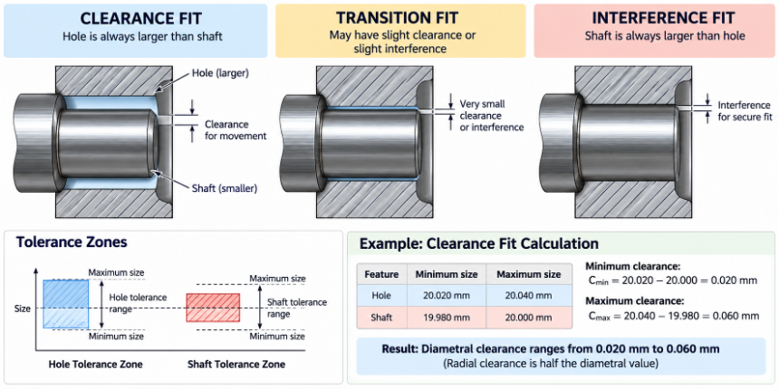
Three basic fit categories cover many mechanical applications.
Clearance fitA clearance fit ensures that the hole is larger than the shaft throughout the permitted dimensional ranges. The difference between the two dimensions provides space for relative movement or assembly.
This arrangement is common in sliding guides, rotating shafts, removable pins, and mechanisms that require easy disassembly. However, more clearance is not always better. Excessive space can allow vibration, impact, misalignment, and uneven wear.
Interference fitAn interference fit occurs when the shaft is larger than the hole before assembly. Installing the components requires elastic deformation, a suitable press, or a controlled thermal assembly process.
Interference fits are frequently used to secure hubs, pulleys, gears, and certain bearing rings. They can prevent relative movement under load, but excessive interference may distort components, increase assembly forces, or damage a bearing.
Transition fitA transition fit lies between clearance and interference behavior. Depending on the actual manufactured dimensions, the assembled parts may have slight clearance or slight interference.
It is useful when accurate positioning is important but the designer does not necessarily want a permanent press fit. Locating components and selected precision assemblies may use this approach.
The important distinction is that a fit describes the dimensional relationship, whereas running clearance describes the space available for movement during operation. A mechanism may have a suitable assembly fit but still experience inadequate running clearance when temperatures rise or components deform under load.
Use Tolerances to Predict the Assembled ResultA nominal dimension is a target, not a guarantee that every manufactured part will have exactly that size. A shaft specified as 20 mm and a matching hole specified as 20 mm may still produce clearance or interference because each feature has its own permitted dimensional variation.
The ISO 286 system provides standardized tolerance classes for linear sizes and defines the terminology used to describe fits. In the United States, ASME B4.2 also describes preferred metric limits and fits for general engineering use. These systems help designers specify consistent, measurable requirements rather than relying on descriptions such as “snug fit” or “slightly loose.”
Calculate the minimum and maximum clearanceFor a clearance fit, the basic calculations are:
C=Dhole,min-Dshaft,max
C=Dhole,max-Dshaft,min
Consider a hypothetical sliding assembly with these dimensional limits:
FeatureMinimum sizeMaximum sizeHole20.020 mm20.040 mmShaft19.980 mm20.000 mmThe minimum clearance is:
20.020-20.000=0.020mm
The maximum clearance is:
20.040-19.980=0.060mm
Therefore, the diametral clearance ranges from 0.020 mm to 0.060 mm, or 20–60 micrometers. The corresponding radial gap is half the diametral clearance when the shaft is perfectly centered.
This calculation establishes the dimensional envelope, but it does not prove that the assembly will slide smoothly under every operating condition. Surface texture, straightness, alignment, deflection, contamination, and temperature can affect actual movement.
Why tolerance zones matterISO tolerance designations combine a letter and a number. The letter indicates the position of the tolerance zone relative to the nominal dimension, while the number identifies its tolerance grade.
For example, H7 is a commonly encountered hole tolerance designation, and h6 is a shaft designation. The letters are case-sensitive because hole and shaft tolerance zones follow different conventions. Neither designation should be interpreted as a universal clearance value: the actual permissible dimensions depend on the nominal size and applicable standard tables.
Engineers should select a complete fit based on the intended function, then verify the resulting minimum and maximum clearance or interference. Choosing a tolerance class simply because it appears frequently on other drawings can produce an unsuitable assembly.
Account for the Conditions Inside the MachineA fit that works at room temperature may behave differently after a machine starts operating. The design must consider the assembled mechanism as a physical system rather than a collection of isolated dimensions.
Temperature and thermal expansionDifferent materials expand at different rates. Even two components made from the same material can experience different dimensional changes if their operating temperatures differ.
For an approximate estimate of uniform thermal expansion:
D=DT
Here, D is the diameter change, is the material's coefficient of thermal expansion, D is the initial diameter, and T is the temperature change.
As a hypothetical illustration, consider a 20 mm steel shaft whose temperature rises by 50°C. Using an illustrative coefficient of \(12\times10^{-6}/^\circ\text{C}\), its diameter change would be approximately:
D=1210-62050=0.012mm
That is a 12-micrometer increase. The example assumes uniform heating and is intended to demonstrate the calculation, not establish a universal material specification.
The relevant quantity for a working fit is the difference between the dimensional changes of the mating components. A housing that heats more than its shaft may increase clearance, while a hotter shaft inside a cooler housing may reduce it.
Bearing assemblies need particular care because mounting fits and operating temperatures can also alter internal bearing clearance. SKF's bearing guidance identifies load, temperature differences, mounting conditions, and running accuracy as important fit-selection factors.
Load, speed, and vibrationMechanical loads can deform shafts, housings, guides, and supports. The direction and magnitude of the deformation matter because a small reduction in local clearance can cause contact, friction, or binding.
Rotating components also experience dynamic effects that a static drawing cannot fully describe. High-speed operation, imbalance, changing loads, and vibration may make excessive looseness unacceptable even when the dimensions technically satisfy the drawing.
For bearing rings, the relationship between the applied load and the ring's motion is particularly important. An inadequately secured ring may creep or rotate relative to its seat, damaging mating surfaces. An interference fit can help prevent this movement, but excessive interference may reduce internal clearance or distort the bearing.
Lubrication and surface finishA sliding interface does not operate on dimensional clearance alone. Its surface texture, lubricant, contact pressure, and movement pattern affect friction and wear.
A larger gap may provide space for lubricant or accommodate expected contamination, but it may also permit unwanted movement. A very small gap may improve positioning while increasing sensitivity to particles, surface irregularities, or thermal growth.
Surface roughness should therefore be specified in relation to the application and manufacturing process. It should not be used as a substitute for dimensional tolerance, geometric control, or an explicit lubrication requirement.
Match the Fit to the Component's FunctionThere is no single fit that suits every moving mechanism. The best starting point is to identify what the interface must do.
ApplicationMain design priorityKey considerationSliding guide or linear bushingSmooth, controlled travelClearance, alignment, lubrication, and contaminationRotating shaft in a plain bearingStable rotationLoad, speed, lubricant film, and operating temperatureGear or pulley mounted on a shaftSecure torque transmissionRelative movement, assembly method, and shaft loadingRemovable locating pinRepeatable positioningPosition accuracy and ease of removalRolling bearingReliable support and rotationRing loading, internal clearance, temperature, and seat geometryTelescoping mechanical assemblyMovement across a travel rangeStraightness, accumulated variation, and resistance to bindingThese are starting points, not final tolerance prescriptions. For example, a gear may be secured by an interference fit, a key, a spline, or a clamping arrangement. The correct choice depends on torque, serviceability, material strength, and the overall assembly design.
For rolling bearings, use the manufacturer's recommendations for the specific bearing type and operating conditions instead of applying generic shaft-and-hole guidance without modification.
How CAD Drawings Help Prevent Fit ProblemsA technically sound fit must be communicated clearly enough for manufacturing, inspection, and assembly teams to reproduce it consistently. This is where 2D engineering drawings and 3D CAD models serve complementary roles.
A 3D model helps designers visualize component relationships, identify interference between assembled parts, and evaluate clearances throughout a mechanism's movement. Parametric modeling can also make it easier to explore dimensional changes and preserve design intent as a component evolves.
However, a nominal 3D model does not automatically communicate all the manufacturing requirements needed to produce a functional assembly. Unless tolerances and relevant specifications are defined, a model may show the intended geometry without establishing acceptable production limits.
A complete manufacturing drawing should communicate the following where applicable:
- Dimensional tolerances: Minimum and maximum acceptable sizes for mating features.
- Geometric dimensioning and tolerancing (GD&T): Controls for features such as position, orientation, form, and runout when these characteristics affect function.
- Surface finish: Requirements for contact surfaces, bearing seats, and sliding interfaces.
- Material specifications: Material properties relevant to strength, stiffness, wear, and thermal behavior.
- Assembly requirements: Fits, fastening methods, lubrication, and installation instructions.
- Inspection requirements: Appropriate measurement methods and acceptance criteria.
GD&T is especially useful when a component must maintain alignment with other features. Two parts may meet their individual size tolerances but still assemble poorly if their axes are misaligned or their functional surfaces are not sufficiently straight.
CAD interference checks can identify obvious geometric conflicts, but they should not be treated as proof that a real mechanism will operate correctly. A more complete evaluation may require tolerance-stack analysis, kinematic analysis, thermal calculations, or physical testing.
Evaluate Tolerance Stacks in Multi-Part AssembliesA mechanism often contains several mating components, each contributing dimensional variation to the final position or movement of the assembly.
Consider a sliding carriage guided by two rails and supported by mounting brackets. Even if each individual interface satisfies its own tolerance, accumulated variation may cause the carriage to bind or become misaligned.
A tolerance-stack analysis estimates how these variations combine.
In a worst-case analysis, the designer combines the relevant dimensional extremes to establish the largest possible variation. For independent dimensions that contribute in the same direction, this is commonly calculated by adding their absolute tolerance contributions.
A statistical approach, such as root-sum-square analysis, may be appropriate when variations are independent and the statistical assumptions are justified. It does not guarantee the same limits as a worst-case analysis.
The appropriate method depends on the consequence of failure. A mechanism that must assemble reliably across all permitted manufacturing conditions may require worst-case verification. A high-volume process with validated capability may support a statistical approach for suitable characteristics.
For moving assemblies, the analysis should consider more than static dimensions. Relevant contributors may include:
- Shaft and bore size variation.
- Rail parallelism and mounting position.
- Bracket deformation under load.
- Thermal expansion.
- Bearing clearance.
- Wear and lubrication conditions.
Identifying the dominant contributors early helps engineers avoid unnecessarily tight tolerances on every component. Instead, manufacturing precision can be concentrated on the features that control actual function.
Common Fit-Selection Mistakes to AvoidSeveral recurring mistakes can undermine an otherwise well-designed mechanism.
Specifying tighter tolerances than necessary. Tighter dimensional limits can increase machining, inspection, and rejection costs. Apply precision where function requires it rather than treating the smallest possible tolerance as the best option.
Ignoring operating temperature. A fit selected only at room temperature may become too tight or too loose after the machine reaches its operating condition.
Using clearance to compensate for poor alignment. Increasing the gap between components may temporarily reduce binding, but it can also increase vibration and uneven loading. Correcting the underlying geometry may be the better solution.
Overlooking assembly and maintenance. A permanent interference fit may be inappropriate for a component that must be replaced frequently. Consider access, removal tools, repair procedures, and expected service life.
Relying on nominal CAD geometry alone. A model without appropriate dimensional and geometric controls may not communicate the requirements needed to manufacture a functional assembly.
Applying bearing fit tables indiscriminately. Bearing type, load direction, ring rotation, shaft construction, housing material, and operating temperature can change the appropriate recommendation. Consult the relevant manufacturer's technical documentation.
A Practical Checklist Before Releasing a Mechanical DrawingBefore finalizing the fit between two moving components, verify the following:
- The function of the interface is clearly defined.
- The required fit category has been selected.
- Minimum and maximum assembled clearance or interference have been calculated.
- Material properties and expected operating temperatures have been considered.
- Loading, speed, vibration, and lubrication requirements have been reviewed.
- Surface finish and geometric tolerances are specified where needed.
- Tolerance accumulation across the assembly has been evaluated.
- Manufacturing and inspection methods can achieve and verify the specified limits.
- Assembly, removal, and maintenance requirements have been addressed.
- The final drawing communicates the intended design unambiguously.
The most reliable fit is not necessarily the tightest or loosest one. It is the fit that consistently delivers the required movement, positioning, load support, and serviceability within the actual manufacturing and operating conditions. By combining dimensional calculations, realistic operating assumptions, tolerance analysis, and clear engineering documentation, designers can reduce avoidable assembly problems without imposing unnecessary manufacturing precision.
Sources- International Organization for Standardization — ISO 286-1:2010, Geometrical product specifications: ISO code system for tolerances on linear sizes. Covers tolerance-zone terminology and the principles of hole-basis and shaft-basis fits.
- American Society of Mechanical Engineers — ASME B4.2, Preferred Metric Limits and Fits. Describes preferred metric limits and fits for general engineering use in the United States.
- SKF — Bearing Installation and Maintenance Guide. Provides technical guidance on shaft and housing fits, mounting, internal bearing clearance, and operating considerations.