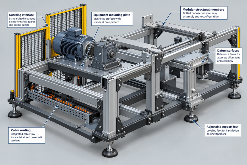

Design Considerations for Modular Machine Frames and Equipment Bases
A modular machine frame must do more than hold components in place. It needs to maintain alignment under load, resist vibration, accommodate maintenance access, and remain practical to manufacture and assemble. Decisions made during the initial design can affect machine accuracy, installation time, future upgrades, and the cost of correcting problems after fabrication.
For engineers developing industrial equipment, the challenge is balancing structural rigidity with modularity. A frame that is easy to reconfigure may introduce additional joints, while a highly rigid welded structure may be difficult to modify or transport. The most effective design starts by understanding how the machine will operate, how its loads travel through the structure, and which interfaces must remain accurate throughout the equipment's service life.
These requirements make accurate drawings and coordinated 3D models important from the earliest stages. Resources coveringMechanical CAD Services in UK can provide additional context on the role of mechanical drafting in communicating dimensions, interfaces, and manufacturing requirements. The central engineering task, however, is to ensure that the frame's geometry, structural behavior, and assembly method work together as one system.
Start With the Load Path, Not the Frame ProfileThe first design decision should be how forces move from the machine's working components into the floor or supporting structure. Choosing a tube size or extrusion profile before understanding those forces can result in a frame that is unnecessarily heavy in some areas and insufficiently stiff in others.
A useful load-path review identifies:
- The weight of motors, gearboxes, tooling, workpieces, guards, and auxiliary equipment.
- Dynamic forces generated by reciprocating parts, rotating machinery, cutting operations, or material handling.
- Horizontal forces from acceleration, braking, impact, and operator interaction.
- Overturning moments created by equipment mounted above the frame's center of gravity.
- Loads introduced during lifting, transportation, and installation.
- Local forces around anchors, mounting plates, and adjustable feet.
Consider a hypothetical machine with a heavy drive assembly mounted at one end of a long rectangular base. Even if the frame can support the total weight, the uneven load distribution may cause local bending or twisting. If precision components are mounted at opposite ends, that deformation can affect their relative alignment.
The solution is not necessarily to increase every member's cross-section. It may be more effective to shorten unsupported spans, introduce cross-members, reposition the equipment, or create a direct structural path between the drive assembly and its supports.
Distinguish strength from stiffnessStrength concerns whether a component can withstand the applied stresses without yielding, fracturing, or otherwise failing. Stiffness concerns how much it deforms under those loads.
A frame can be strong enough to avoid structural failure yet too flexible for its intended function. For machine tools, inspection systems, automated assembly equipment, and precision handling systems, this distinction is especially important.
Engineers should evaluate both member stresses and overall deflection. Where vibration matters, they should also consider the frame's natural frequencies and how they interact with operating speeds and excitation sources.
Choose a Modular Architecture That Matches the EquipmentModularity is not simply a matter of dividing a frame into smaller pieces. It is a decision about which parts should be independently manufactured, transported, assembled, replaced, or repositioned.
Three common approaches serve different needs.
Frame architectureMain advantagesImportant limitationsWelded steel frameHigh structural continuity; relatively few mechanical jointsWelding distortion, finishing requirements, and limited reconfigurationAluminum extrusion frameFlexible assembly, accessible fastening systems, and straightforward modificationJoint stiffness, local connection capacity, and vibration behavior require attentionBolted steel modular frameStrong, replaceable structural connections and adaptable layoutsMore interfaces, fasteners, assembly work, and potential alignment adjustmentsA hybrid design can combine these approaches. For example, a welded steel base may support heavy machinery, while bolted extrusion sections carry guards, sensors, cable trays, and operator interfaces.
This arrangement places structural demands on the components best suited to handle them while preserving flexibility where frequent changes are likely.
Decide which interfaces must be standardizedStandardizing every component is rarely necessary. The priority is to standardize interfaces that influence assembly, maintenance, and future expansion.
Useful candidates include:
- Equipment mounting-hole patterns.
- Reference datums and locating features.
- Fastener sizes and access clearances.
- Guarding attachment points.
- Cable-routing and pneumatic-service interfaces.
- Lifting points and designated support locations.
- Connections between the main base and removable modules.
A repeatable interface allows one module to be replaced without redesigning the entire machine. However, nominally identical hole patterns do not automatically guarantee interchangeability. Position tolerances, surface flatness, locating features, and the assembly sequence must also be controlled.
Control Geometry Through Datums and TolerancesA modular frame can be easy to assemble and still fail to locate its components accurately. The reason is often a mismatch between how dimensions are specified and how the machine is actually assembled.
A dimensioned drawing should establish a clear reference system. Datums provide the geometric references from which dimensions and tolerances are defined. For a machine base, these may include a primary mounting plane, a longitudinal reference edge, and a transverse locating face.
With a consistent datum scheme, engineers can define the position of critical interfaces without relying on a long chain of dimensions measured from one feature to the next.
Avoid unnecessary tolerance stackingTolerance stack-up occurs when variations in multiple dimensions accumulate across an assembly. In a modular machine, the effect can become noticeable when several brackets, plates, rails, and connection points separate two components that must remain aligned.
Imagine three connected modules, each with a nominal interface offset of 0.5 mm. If all three offsets occur in the same direction, the accumulated displacement could reach 1.5 mm. This is a simplified hypothetical example, not a prediction of actual manufacturing accuracy; the result depends on the specified tolerances and how the dimensions relate to one another.
To reduce unwanted accumulation:
- Dimension critical interfaces from common functional datums where practical.
- Identify which surfaces establish location and which merely provide support.
- Use locating pins, shoulders, or machined reference faces where repeatable positioning is required.
- Allow clearance at noncritical joints rather than imposing unnecessarily tight tolerances everywhere.
- Verify the assembled tolerance chain for components that must align across module boundaries.
Geometric dimensioning and tolerancing (GD&T) can communicate requirements for position, flatness, perpendicularity, and other geometric characteristics. The appropriate controls depend on the function of each feature. A decorative cover bracket does not normally require the same precision as a rail mounting surface or a precision spindle interface.
General tolerance standards can help define default limits, but they do not replace function-specific requirements. Engineers should identify the applicable standard and edition in the drawing package, then explicitly specify critical dimensions and geometric controls.
Account for Welding, Machining, and Assembly SequenceA frame's finished geometry depends on how it is manufactured. Designing only the ideal CAD model can overlook the distortions, access limitations, and process variations that appear during fabrication.
Welded structures need distortion controlWelding introduces localized heat, which can cause contraction and distortion as the structure cools. Long members, thin plates, and asymmetrical weld arrangements may be particularly sensitive to changes in geometry.
Practical design measures include:
- Using a balanced weld sequence where appropriate.
- Avoiding unnecessarily large welds when smaller welds meet the engineering requirements.
- Providing suitable fixture and clamping access.
- Locating critical machined features so they can be finished after welding when necessary.
- Establishing inspection points for flatness, squareness, and mounting-hole position.
For a precision machine base, machining mounting pads after the main weldment has been fabricated may provide more reliable reference surfaces than attempting to hold final precision through welding alone. Stress-relief treatment may also be considered where the application, material, fabrication process, and machining strategy justify it.
These choices should be agreed upon with the fabricator before the drawing package is released. Otherwise, a design may specify final geometry without providing a realistic process for achieving it.
Design bolted joints for repeatable assemblyBolted joints introduce different considerations. Their performance depends on fastener selection, joint geometry, contact surfaces, preload, and the forces the connection must resist.
Clearance holes make assembly easier but do not necessarily establish accurate positioning. If a module must return to the same location after removal, separate locating features can be more dependable than relying on bolt clearance alone.
Engineers should also consider tool access, washer clearance, edge distances, thread engagement, and whether the fasteners can be tightened and inspected after neighboring components are installed.
A good assembly drawing communicates not only where a component belongs, but also how it can physically be installed, adjusted, and removed.
Use 3D CAD to Test the Real AssemblyA three-dimensional model is particularly valuable when a frame contains multiple modules, moving mechanisms, guards, electrical enclosures, and service connections. It helps engineers identify conflicts before manufacturing begins.
However, a visually complete model is not automatically a manufacturable design. CAD review should focus on practical questions.
Will the parts fit? Check interference between structural members, brackets, fasteners, motors, and neighboring assemblies. Include the actual dimensions of purchased components rather than relying on approximate placeholders.
Can the parts be assembled? A bolt may be present in the model yet impossible to tighten because a cross-member blocks the wrench. Check installation direction, tool clearance, lifting access, and the order in which parts must be fitted.
Can the equipment be serviced? Confirm that technicians can reach lubrication points, filters, electrical connectors, adjustment screws, and replaceable components without dismantling major structural sections.
Can the modules be transported? Consider the size and weight of individual sections, available lifting equipment, access through doors, and the stability of the assembly during handling.
Can the model be manufactured from the released information? Every fabricated part should have the dimensions, material information, tolerances, and finishing requirements needed by the relevant supplier.
Parametric modeling can make these reviews more efficient. If the distance between two modules changes, properly defined design relationships can update associated members and interfaces. Poorly structured models, by contrast, may contain fragile dependencies that break when a key dimension changes.
The objective is to capture design intent: the rules that explain why features have their particular positions and relationships.
Evaluate Vibration and Operating ConditionsStatic load calculations are not always sufficient for machinery that operates continuously or performs repetitive movements. A frame may deflect acceptably under a stationary load but vibrate excessively when motors, pumps, conveyors, or reciprocating mechanisms are running.
Vibration depends on the mass, stiffness, damping, support conditions, and excitation forces of the complete system. Connections between modules matter because their behavior can influence the stiffness of the assembled structure.
For demanding applications, finite element analysis (FEA) can help evaluate structural deformation and stress. Modal analysis can estimate natural frequencies and associated mode shapes, helping engineers identify potential resonance concerns. These simulations should use realistic boundary conditions and representative loads; their results are only as reliable as the assumptions behind the model.
The surrounding installation also matters. An otherwise rigid frame can behave differently when installed on a flexible floor, mounted on isolators, or anchored to a substantial foundation.
Before selecting vibration-control measures, engineers should identify the dominant source of excitation and the transmission path. Depending on the problem, suitable changes may include increasing local stiffness, revising support locations, improving joint design, balancing rotating components, or selecting appropriate isolation mounts.
Simply adding mass is not a universal solution. It can alter natural frequencies without necessarily eliminating the underlying problem.
Integrate Safety, Access, and Installation RequirementsThe frame supports more than the machine's working components. It often carries guards, access doors, cable trays, electrical cabinets, sensors, pneumatic equipment, and operator interfaces. These items should be coordinated with the structure rather than added after the main design is complete.
Safety requirements must be considered as part of the overall equipment design. For example, OSHA's machine-guarding guidance addresses hazards associated with moving parts and includes requirements for safeguarding machinery and anchoring fixed equipment in applicable US workplaces. Designers must also determine which regulations and standards apply in the intended installation location.
Occupational Safety and Health Administration+1
Several practical details deserve early attention:
- Guarding: Provide suitable mounting points and sufficient clearance for guards, interlocks, and access doors.
- Maintenance: Allow components to be removed without cutting, welding, or dismantling unrelated modules.
- Utilities: Reserve routes for electrical cables, pneumatic lines, coolant, and lubrication systems.
- Leveling: Select support feet, shims, or leveling systems appropriate to the floor and alignment requirements.
- Anchoring: Check the required anchor locations and the capacity of the supporting floor or foundation.
- Handling: Identify lifting points and confirm that the structure can be moved safely using the intended equipment.
Installation conditions should be reflected in the drawings. A base designed for a level factory floor may need a different support strategy if it will be installed on an uneven surface or transported between facilities.
Make the Drawing Package Ready for ManufacturingThe final CAD package should translate the design into information that fabricators, machinists, assemblers, and inspectors can use without relying on assumptions.
A complete release may include a 3D assembly model, individual part drawings, fabrication drawings, an assembly drawing, and a bill of materials (BOM). The exact deliverables depend on the complexity of the equipment and the responsibilities assigned to each supplier.
Each part drawing should communicate the information relevant to manufacturing and inspection, including:
- Material grade and section specifications.
- Critical dimensions and applicable tolerances.
- Weld symbols and weld requirements, where applicable.
- Surface finish or coating requirements.
- Machined interfaces and geometric controls.
- Hole sizes, thread specifications, and fastener details.
- Identification numbers and drawing revisions.
File formats should be selected according to the recipient's workflow. Native CAD files retain editable design features when supported by the receiving software. STEP is commonly used to exchange three-dimensional geometry between CAD systems, while DWG and DXF support many two-dimensional drawing and geometry workflows. PDF is useful for distributing controlled drawing documents for review and production reference.
Neutral exchange formats may not preserve all native parametric features, constraints, or manufacturing metadata. A file should therefore be checked after export, particularly when critical dimensions or complex assemblies are involved.
Revision control is equally important. If a mounting-hole pattern changes after fabrication has started, the supplier must be able to identify which components and drawings are affected. Consistent part numbering, revision identifiers, and release records help prevent outdated information from being used on the shop floor.
A Practical Review Before Releasing the DesignBefore approving a modular machine frame for production, review the following questions with the engineering and manufacturing teams.
Design-release checklist0 of 10
- The load cases and structural load paths have been identified.
- Strength, deflection, and relevant vibration requirements have been evaluated.
- The frame architecture matches the required level of modularity.
- Critical interfaces have defined datums and appropriate tolerances.
- Welding distortion and post-fabrication machining have been considered.
- Fasteners, locating features, and assembly tools are accessible.
- Maintenance, guarding, utilities, lifting, and anchoring have been coordinated.
- The CAD assembly has been checked for interference and installation access.
- Manufacturing drawings, material specifications, and the BOM are complete.
- File exports and revision identifiers have been verified.
0% reviewed
Reset checklist
A checklist cannot replace engineering calculations, safety assessments, or inspection, but it can expose gaps before they become expensive production problems.
The most successful modular frames are designed around the requirements of the complete machine rather than the geometry of individual members. Structural performance, repeatable alignment, manufacturing constraints, service access, and controlled documentation all influence the final result. Addressing these factors together creates a frame that is not only buildable, but also practical to install, maintain, and adapt over time.
Sources- ISO 5459:2024 — Geometrical product specifications: Datums and datum systems. Reference for datum terminology and datum systems in technical product documentation.
- ISO 1101:2017 — Geometrical tolerancing. Reference for geometric tolerances of form, orientation, location, and run-out.
- Siemens — Modal analysis. Technical overview of natural frequencies, structural modes, and vibration behavior.
- OSHA — Machine Guarding Standards. Reference for applicable US machinery safeguarding requirements.

Kraft Paper Price Trend 2026 | Price Trends, Forecast, Chart, Prices a...

Fluff Pulp Price Trend Q3 2026 | Global Price Trends, Forecast, Chart,...
Os Jogos Mais Populares e Como Escolher o Seu Favorito
Os Jogos Mais Populares e Como Escolher o Seu Favorito

Akemi: Ingredients, Side Effects, Price, and Customer Feedback
Akemi Coffee Boost is marketed for weight management and metabolic support. Its ingredient...